


How to install the Ikos Controller Cosmos hydroponic system
This article is also available in: Español · Français
This guide describes the full installation and commissioning procedure for the Ikos Controller Cosmos in hydroponic crops, together with the technical specifications of the unit and each of its sensors. It is written for the installation technician and serves as a reference document for the customer.
1. Equipment description #
An advanced measurement system for hydroponic crops, designed to operate wirelessly and autonomously thanks to its rechargeable battery and solar panel.
It provides comprehensive crop monitoring through a set of high-precision sensors, ideal for optimising yield and plant health.
Beyond making it easier to control growing conditions, the system allows more efficient management of water and energy, contributing to more sustainable and profitable production.
System components #
- Ikos Controller · datalogger and transmission
- Ikos Tensiometer · substrate tension
- Ikos Multisensor · moisture, EC and temperature
- Ikos DPV (H&T) · temperature and humidity
- Ikos PAR sensor · radiation
- Drainage gauge · weight and tank
- Volumetric meter · irrigation volume
- Solenoid valve · line control
Key features #
- Multiple communication modules (UNB or GPRS) for efficient connectivity.
- Several sensors can be connected to each device, allowing complete monitoring.
- Powered by a rechargeable battery and solar panel for continuous, sustainable operation.
- Easy to install and portable, suitable for different crop types and configurations.
2. Datalogger connectivity schematic #
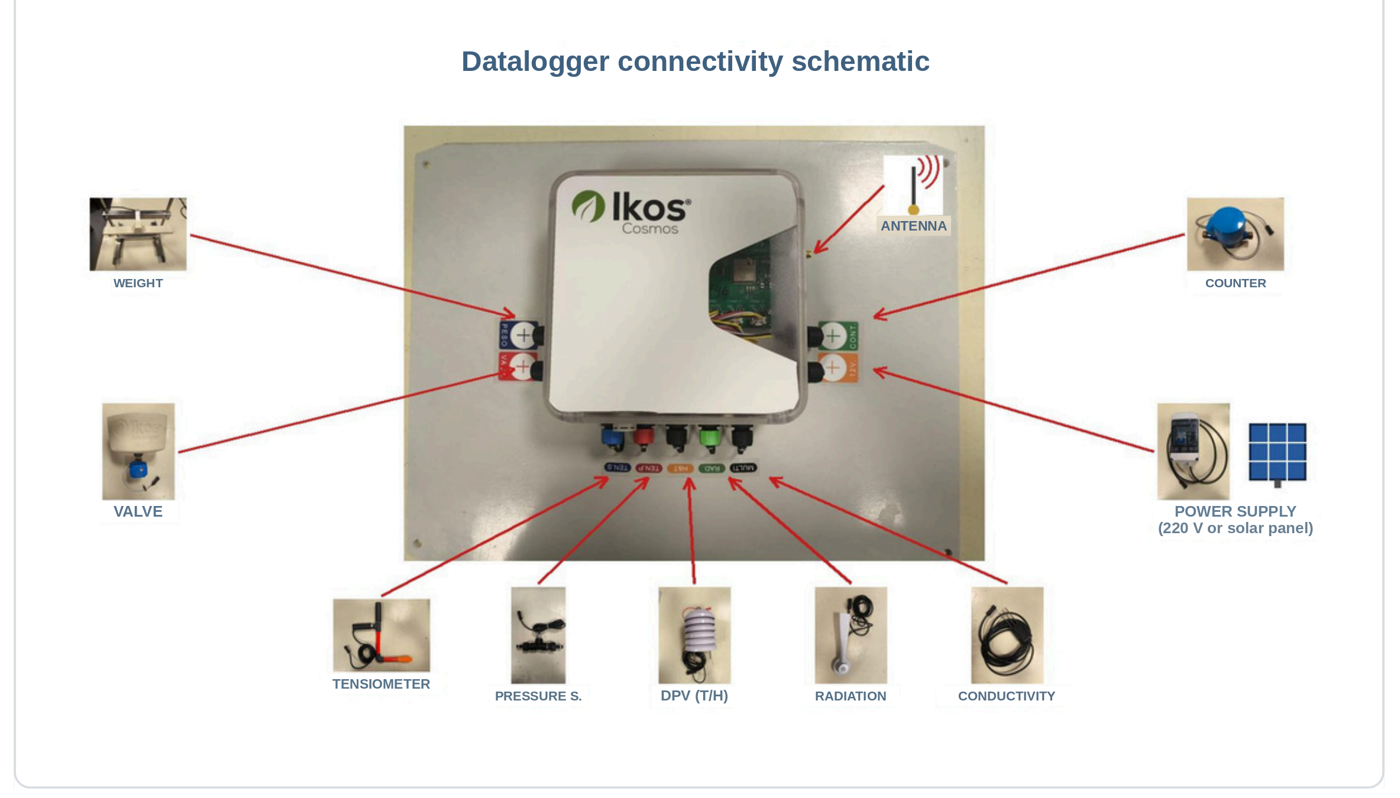
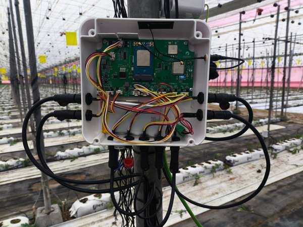
Before you start, familiarise yourself with the connections on the box. Each sensor has an assigned position on the datalogger, identified by its label: WEIGHT, VALVE, TEN·S, TEN·P, H&T, RAD, MULTI, CONT and 12 V. The antenna connects on the upper side.
3. Before you start · key recommendations #
- Tray location: do not install it under a water channel, and choose the most representative bags on the line.
- No leaks: the drip line must be free of leaks, both in the pipe and in the drippers, as this would affect the drainage calculation.
- Levelled tank: the tank must discharge as much water as possible when emptying; nothing should be in contact with the tank or the load cell.
- Registration and calibration: weight calibration is always carried out with an Ikos technician, who sends the calibration codes (a 200 g reference weight is included).
- Extension cables: volumetric meter → 25 m; radiation sensor, weight and valve → 2.5 m each.
4. Installation procedure #
Step 1 · Choosing the installation point #
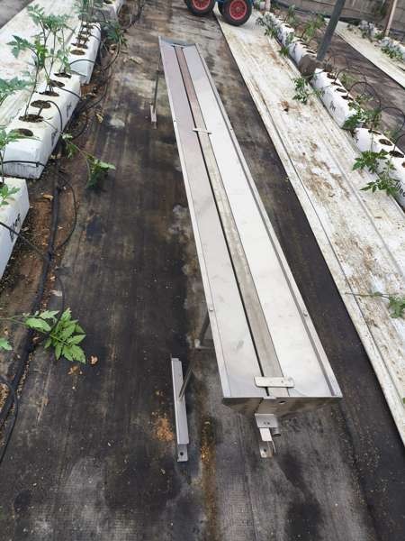
Select the most suitable installation point. Do not install the tray under a water channel and choose the most representative bags. Find the mid-point of the line, place the tray next to the supports and join them with the screws.
Step 2 · Positioning the tray #
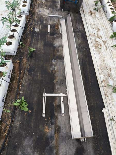
Remove the 2 plant bags you are replacing with the tray and put it in their place, with the water outlet facing the slope of the site to help the water drain. Place the growing bar in the centre.
Step 3 · Levelling the tray #
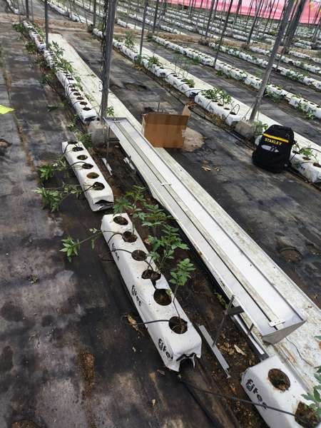
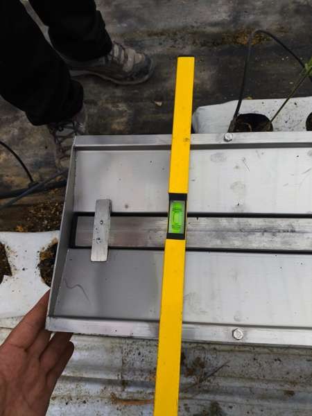
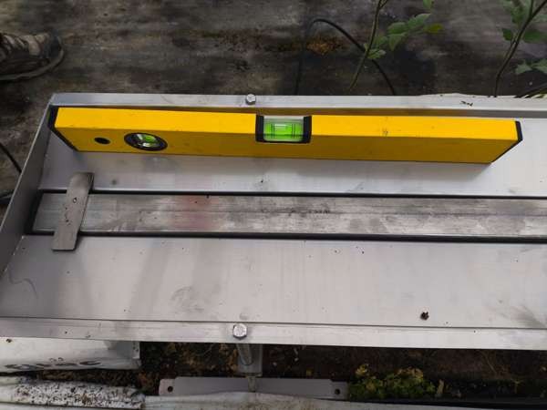
Using the screws that join the tray to the legs, adjust the tilt with a spirit level. Level across the width and apply the slope along the length, aiming for the fall towards the water outlet connection.
Step 4 · Installing the bags with their drippers #
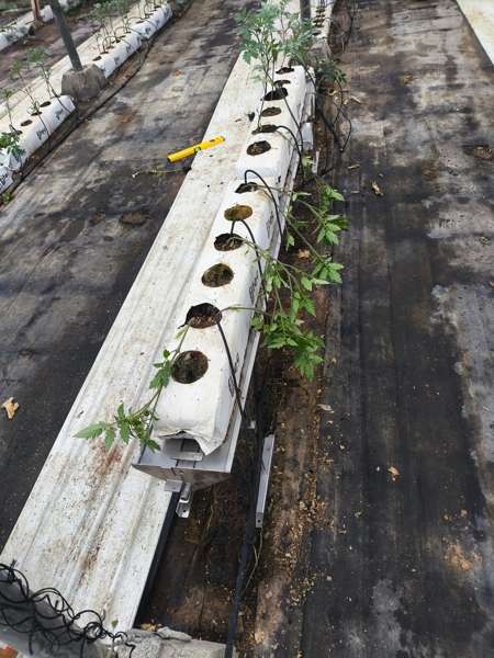
Install the plant bags with their drippers on the tray, once it is in place and levelled.
Step 5 · Installing the weight bracket and tank #
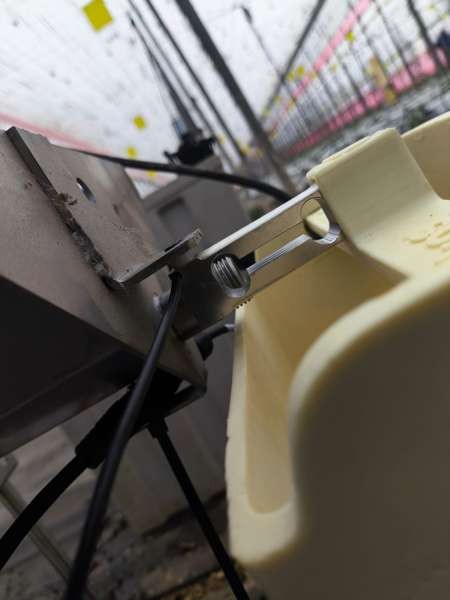
Install the weight bracket with two screws and its spacers in the position shown, then fit the tank. Both the load cell and the tank have a connector that must be joined to a 2.5 m extension cable, which in turn connects to the matching connector on the box.
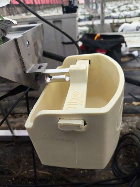
Step 6 · Installing the sensors #
Tensiometer: place it in the centre plant, with the ceramic facing the plant. On large or more mature plants, install it from the side. In both cases the ceramic must sit in the centre of the bag at mid-height.
EC sensor: install it the same way, making sure the dripper falls vertically onto the sensor prongs.
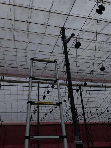
Radiation sensor: install it facing south, above the plants, so they never cover it during the cycle.
Temperature and humidity sensor (DPV): install it at canopy height.
Connect each sensor to its matching position on the datalogger.
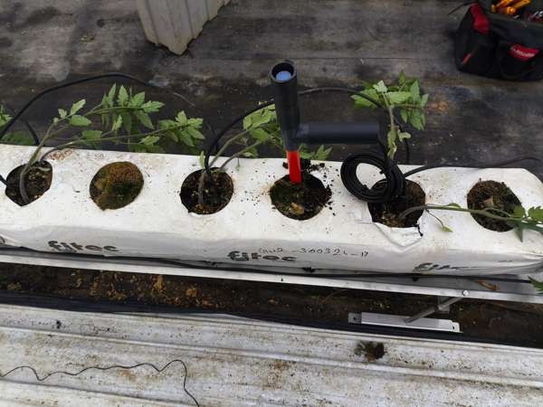
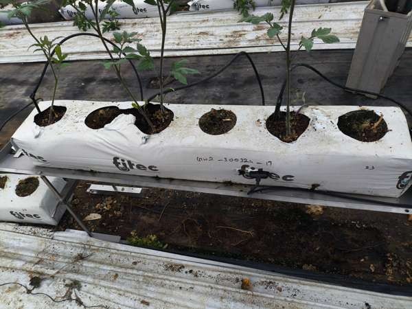
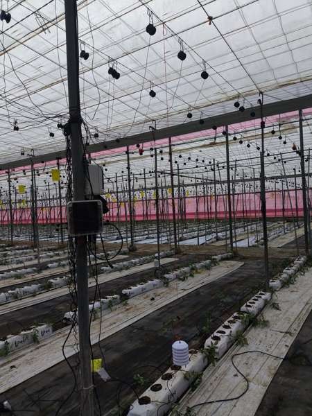
Step 7 · Installing the meter #
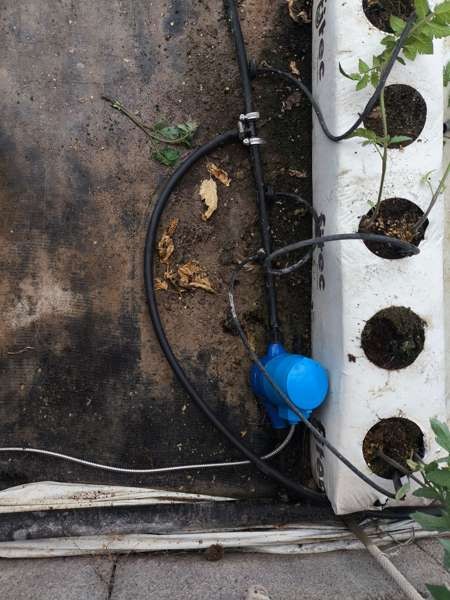
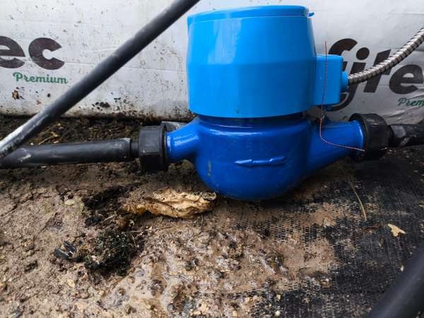
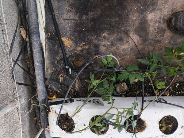
Install the meter at the start of the dripper line. Mind its orientation: the arrow shows the direction of the water. If it feeds fewer than 40 drippers, connect another nearby pipe after the meter. Important: dripper lines must end in a plug and must not be joined to another secondary pipe.
Step 8 · Installing the power supply box #
Install the 12 V power supply box near the datalogger, power it from 220 VAC and connect it to the datalogger.
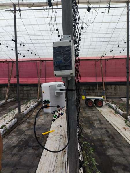
Step 9 · Installing and commissioning the datalogger #
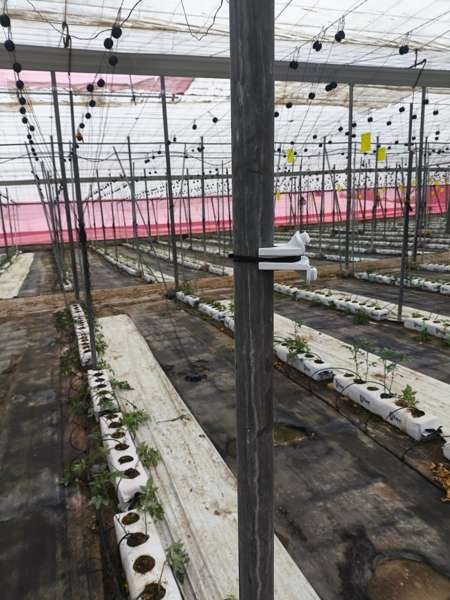
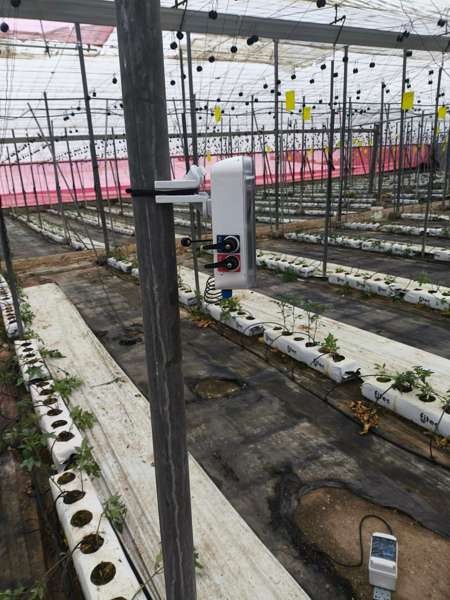
Fit the datalogger box bracket to the post using a metal clamp or plastic cable ties, and mount the box where the other sensors connect. Connect the antenna and the battery to the electronic board. Once the sensors are installed, calibrate the weight and register the unit. Finish by closing the box.
5. Important notes #
- Weight calibration: always carried out with an Ikos technician, who sends the calibration codes; the customer helps by placing the weight when the technician says so. The weight supplied is a 200 gram unit.
- Drainage calculation: once installation is complete, enter the number of drippers on the tray and the number of drippers fed by the line meter. The system uses that data to calculate drainage for each irrigation.
- Levelling the tank: once in place, add a little water to check that it is properly levelled and does not pool at the sides. Nothing must be in contact with the tank or the load cell, since any extra weight would simulate water that is not there.
- Leaks: the drip line must be free of leaks, both in the pipe and in the drippers, as this would affect the drainage calculation.
- Extension cables: the volumetric meter includes a 25 metre extension cable. The radiation sensor, the weight and the valve each include a further 2.5 metre cable to connect to the datalogger.
6. Technical specifications #
Ikos Controller #
| Power supply | Li-Po, 3.7 V, 4400 mAh |
| Solar panel | 3.6 W · 6.6 V |
| Microprocessor | ARM Cortex-M0+ 32 bit |
| Communications | DUAL: Ultra Narrow Band (UNB) or GPRS |
| Output signal | 3 analogue inputs · 1 RS485 input · 1 I2C |
| Number of sensor inputs | 5 |
| Connectors | 4 × M12, 4 pins |
| Dimensions | 161 × 161 × 80 mm |
| Weight | 600 g |
| Colour | Grey |
| Additional button | ON-OFF · LED push-button switch |
| Protection rating | IP 65 |
| Accessory | Mounting anchor |
Ikos Tensiometer #
| Measurement range | 0 – 1000 mbar |
| Power supply | 5 V |
| Length per tensiometer | 30 cm |
| Accuracy | 0.5 % |
| Overload pressure | 150 % FS |
| Temperature compensation range | -10 °C ~ 70 °C |
| Operating temperature range | -30 °C ~ +70 °C |
| Zero temperature coefficient | 0.3 % FS / 10 °C |
Ikos Multisensor #
| Humidity range | 0 – 100 % |
| Temperature range | -30 °C ~ +70 °C |
| Conductivity range | 0 – 20 mS/cm |
| Output signal | RS485 |
| Response time | < 1 s |
| Power supply | 5 V |
| Effective measurement area | Ø 70 mm · height 70 mm |
| Encapsulation | ABS |
| Operating temperature range | -40 °C ~ +80 °C |
| Protection | IP68 |
| Storage | 10 – 60 °C @ 20 % ~ 90 % RH |
Ikos DPV pendant (H&T) #
| Voltage | 5 V |
| Output signal | I2C |
| Operating range | Temperature: -40 °C ~ +85 °C · Humidity: 0 – 100 % · Pressure: 300 – 1100 hPa |
| Resolution | DPV: 0 – 10 kPa · Temperature: 0.01 °C · Humidity: 0.008 % |
| Accuracy | Temperature: ±1 °C · Humidity: ±3 % · Pressure: ±1 Pa |
Ikos PAR radiation sensor #
| Spectral range | 400 – 700 nm |
| Resolution | ± 5 % |
| Output signal | RS485 |
| Measurement range | 0 – 2500 µmol/m²·s · 0 – 2000 W/m² |
| Operating range | Temperature: -40 °C ~ 80 °C · Humidity: 0 – 100 % |
Ikos volumetric meter #
| Power supply | 5 V |
| Output signal | RS485 |
| Maximum distance | 1000 m |
| Protection | IP68 |
| Operating range | Cold water: 0.1 °C ~ 30 °C · Hot water: 0.1 °C ~ 90 °C |
Ikos drainage gauge #
| Water tank | Fibre, green |
| Structure | Metal |
Ikos solenoid valve #
| Model | CWX-15 |
| Voltage | 12 V |
| Operating current | Max. 100 mA |
| Opening / closing time | < 5 s |
| Control mode | Contact |
| Pressure | Max. 1.0 MPa |
| Power | < 3 W |
| Temperature range | 0 – 100 °C |
| Valve size | DN20 |
| Protection | IP65 |
| Product life | 100,000 cycles |
Any questions? We are here to help! #
- 👉 OPEN A TICKET in the app · How? See here
- 👉 Switchboard: +34 950 50 51 50 (Mon-Fri, 8:00 to 16:00)
- 👉 Support email: [email protected]
- 👉 Customer service: +34 651 674 870 (Mon-Fri, 8:00 to 16:00)
- 👉 Support via WhatsApp: wa.link/boec9r (Mon-Fri, 8:00 to 16:00)
- 👉 IKOS website: ikosadvanced.com